Thursday, 20 December 2018

Dashboard Instrument layout

Attention has now turned to the dashboard and in particular the layout for the instruments. I have decided to go with the Smiths international flight gauges and they have a lead time of 5 - 6 weeks from GBS so that gave me ample time to look at how I will layout the instruments.

To be honest there is not alot of variation you can do with this, more personal preference if you have say the rev counter directly in front of you or the speedo. the remaining auxiliary gauges run right to left in whatever sequence you want/fancy. 

Recognising the relative minimal variation i decided to use the aluminium instrument surround GBS supply - this gives a nice template to use as a mark up for where the holes get drilled. Out withe masking tape and marker pen it is then!

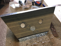
All marked up, its time to get drilling - remember you are drilling glass fibre - it is not nice to breath in, it can be a skin irritant so "suit and boot" accordingly! (Health and Safety speech over with!)

I used a step drill bit to drill through several times to widen the hole and then a barrel sander bit on the drill to remove the remaining bits of glass fibre in each aperture.

end result (apart from alot of glass fibre dust) as follows....

The surround was then polyurethane sealed into position and we now awiat the dials to come through from GBS


Sunday, 29 July 2018

Bonnet Catches

Useful time to look at the bonnet catches and clearly there is an amount of lining up to do as each catch comprises two parts (obviously!) which fit either side of the bonnet and body.

Reading several other blogs a template / jig seems the order of the day which will ensure the catch correctly lines up on the bodywork and holes end up being drilled in the right place!

Hopefully the photos do this part justice, suffice to say a scrap piece of wood, some blue tack and a sheet of paper will be needed.

I first screwed down the black lower end of the catch onto the wood with the paper between the catch and piece of wood. Taking the blue tack I applied that to the paper and then it was a case of carefully positioning the top catch in the black half and pressing down onto the blue tack - this gave me a clue where the top catch fitted in relation to the bottom part.


Once happy with that positioning I screwed through the blue tack to give me my centre hole for the top catch, removed the blue tack and screw, positioned the top catch over the freshly located hole, re- screwed back in and drew round all the parts. The end result is the relative positions of the top and bottom catch are established and that in turn can be used to create the cardboard template.


 Template done,  it was simply a case of transplanting those measurements onto the bonnet and bodywork, carefully drilling the holes and riveting into place - (I had to bend the riveting pin slightly for my riveter to fully pull through the pin and ensure a good grip from the rivet). repeat four times and the bonnet catches should be nicely setup and positioned correctly thus enabling the bonnet to be clipped down securely.


Bonnet - Initial Fit

Its getting to the point where I need to see how the bonnet fits in relation to the scuttle and nosecone. 

Before fitting I attached the bonnet edging trim to both ends which simply knocks in with a rubber mallet (there is a thin bead of glue inside the trim to adhere to the bonnet edge).

I then offered the bonnet up to the scuttle and nosecone (this is temporarily fitted into position) and ratchet strapped front and aft to enable it to form to the shape. Initial indications seem ok - it is slightly proud along the front edges on both sides where the curve is not fully following the curvature of the nosecone . Fit to the scuttle seems good with no obvious area where it is sitting proud.

Clearly some fine tuning to be done and hopefully the gaping referred to above will resolve with the fitment of the bonnet catches and bonnet locating pins...


Saturday, 9 June 2018

Auxiliary Control Panel

Simple job for a Saturday morning, took the opportunity to drill the holes and position the auxiliary switches into the lower instrument panel.

The beauty of the kitcar is each one is individual. I elected to fit the 12v socket, fog lamp and horn switches tot he panel but have for now left room for a starter button which i also fancy fitting (probably when Iva'd and on the road)


so with the switches selected and layout marked out on the panel, time to get to work with the stepped drill bit and carefully drill the holes not getting too carried away with drilling too much!! - little steps and keep checking until each switch fitted nicely through.

Clean up the swarf, remove the masking tape and hey presto holes drilled ready for the switches


Sunday, 6 May 2018

S/S Back Panel Trim & footwell Trim

Grabbed a quick half hour on the car this afternoon, not wanting to get too engrossed in something overly complicated so looking through my Christmas presents Santa kindly left me and the back panel trim / footwell trim seem nice easy pieces to get fitted!

Apart from removing the protective film and cleaning up (which took all the time!) the rear panel trim is simply glued into position with the Polyurethane Sealant and clamped into position to ensure it nicely adheres to the panel.

Provides a nice neat finish to the back panel


Same goes for the footwell trim - these need some filing and trimming to ensure a nice tight fit over the chassis frame but once in place they grab the carpet and will not move anywhere fast!


Sunday, 29 April 2018

Headlamps

Time to give the car some eyes (as my wife refers to them, to be honest I think it does now I look at it!)


Some assembly of the headlights is needed prior to fitment namely remove the stock wiring which comes with the lights, fit a bulb and fit the GBS headlamp / sidelight looms.

The loom will also need some connectors crimping onto the wires prior to connecting into the main wiring loom.

Obviously they need final alignment prior to IVA but until I have power on the wiring loom that can't be completed until near the end of the build


Sunday, 22 April 2018

Fuel pump and starter motor wired in

Managed to grab a quick half hour in the garage and some wiring connections can be made to the fuel pump and starter motor now the engine wiring loom is fully routed.

Simple task of crimping some lugs to the wires - making reference the GBS wiring diagram!


Monday, 2 April 2018

Throttle cable

I expected this to be a nice quick job but it proved far from the case and as I type it is not fully resolved...bear with me and I can explain..

The throttle cable needs some "customisation" to fit to the air intake butterfly valve. If you proceed to fit the cable straight off the shelf, when connected up, throttle travel opens the valve no more than 10% of its full required throw.

So...first piece of customisation... the plastic end connector needs approx 2cm removing off the threaded end and on the piece which screws onto the threaded end that also needs trimming back - hope the pictures below explain that more clearly...


The smaller "pyramid" shaped piece then clips into the butterfly valve frame:


The above customization provides sufficient throttle throw and fully opens the butterfly value.

The throttle cable routing is the next puzzlement...running down the outside chassis rails whilst trying to avoid contact with suspension mounts / steering column is a challenge and although I have routed it I am not happy with how it currently sits...There seems too much cable for the distance it needs to run from the pedal box to the butterfly valve.

So a frustrating session on the build, whilst i have got full throttle travel I am not happy with the cable routing... I am now starting to wonder if I have the RHD Throttle assembly - have I been given the LHD in error? is there a difference between LHD and RHD throttle cables even? - I need a chat with GBS to resolve.


Saturday, 10 March 2018

Inlet Manifold to Plenum

jumping around the build somewhat now... Clutch, front brakes and now back to the engine bay and a re-visit to the plenum.

The GBS plenum needs mating to the modified inlet manifold. This is achieved by gluing the two components together using the Polyurethane Sealant thus preventing the plenum drawing in air through the sides of the plenum rather than through the throttle.  

It is worth getting a selection of "G" clamps to hand for this task as they are invaluable for ensuring the two components are seated together in a flat manner thus maintaning a tight air seal between the parts.

I also used some nuts and bolts as extra pressure to the sealant whilst it cured.

Don't use too much sealant, a nice even smear across the face of the inlet manifold should suffice, when you mate the two parts together ensure none of the sealant seaps into the inlet openings, wipe away with a white spirit soaked cloth.

Its a case of being patient and leaving to dry for a few days before undoing the "G" clamps and nuts and bolts.

Whilst the unit was gluing together, I also fitted the air temperature sensor as I noted access with a spanner to this is restricted once it is fixed onto the engine block.


Front Brake Disc and Calipers

Moving on from fitting the clutch cable, I turned to getting the front brake discs and calipers assembled and fitted onto the hubs.

These are reconditioned calipers from GBS fitted to new grooved vented discs.

Fitment seems straightforward... disc goes over the hub bolts and this in turn is held in position with a couple of wheel nuts. (the countersunk hole in the disc is a puzzlement, not sure if I should be doing anything with that, although there is no hole in the hub for this to align against in turn take a bolt/nut..?)

The caliper bolts to the hub with 2 x M35 bolts - I noted some builds have found the bolts bind on the disc when tightened up and may need a washer to pack out -I did not seem to have this issue, so left with no washers

Finally I connected the braided brake hose to the caliper.

above repeated for both sides - All that remains is for the brake pads to be fitted, brake fluid filled and the brakes bled - subject to any leaks in the union joints on the cooper brake circuit we should be "good to go" on the braking.


Clutch cable fitted

Recent trip across to GBS garnered a few purchases including the clutch and throttle cable. I'll come to the throttle cable later however the clutch cable is a nice easy fit.

Reading several builds and talking to GBS, "notching" a nyloc nut seems the way to go in terms of fitting the cable to the bell housing. whilst the end of the cable slips over the clutch fork that extends outside the bellhousing.

the other end, passes through the pedalbox and connects to the clutch pedal via a "fork" connector - Note the pedal hole will need opening up  and whilst hindsight is a wonderful attribute I wish I had done that before the pedals were fixed in!

As you can see from the photo below, the initial line up of the cable through the pedalbox is skewed to the right hand side of the panel - not wishing this to start binding on the panel I subsequently opened up the hole a little more to remove any risk of it binding and causing any friction. 

Sunday, 25 February 2018

Front hubs / steering rack

Now the Gaz shocks are in position on the front suspension, the front hubs can be positioned and connected to the upper and lower wishbones.

In turn the steering rack can also be connected to the hubs and as demonstrated by the video below, I now have steering!