Showing posts with label Cleco. Show all posts

Saturday, 9 April 2016

Rear Panel - Part 1

Well, the time has come... I have to bite the bullet and give consideration to fitting what most builders consider the hardest piece of the zero build - forming and fitting the rear panel.

It looks daunting when you see the single largest piece of steel flat on the floor and I profess to have spent alot of time reading fellow build blogs, studying photos and basically building up the courage to jump in and get the panel formed.

After reading the various blogs and techniques I also asked the factory how they did it more to confirm some understanding but I guess to see if they had any secret alchemy they used to create this major panel.

Truth be told.. the GBS way of of construction was what I ultimately followed and I will share with you below the technique they used.

So one Saturday set aside with no distractions, plenty of space time to build a rear panel:
  • I covered the patio table with some old carpet/towels and sat the rear panel onto the table top - back down. the panel is quite weak so make sure it is evenly supported.
  • First thing, do not try and roll the side at this point, you need to do some prep work before some bends are put into the panel. 
  • The tabs along the top edge and sides of the under section need bending 90deg, the top edge toward the front of the car, the under section upward. Precision doing this will help later. bend from the bottom of the slots.
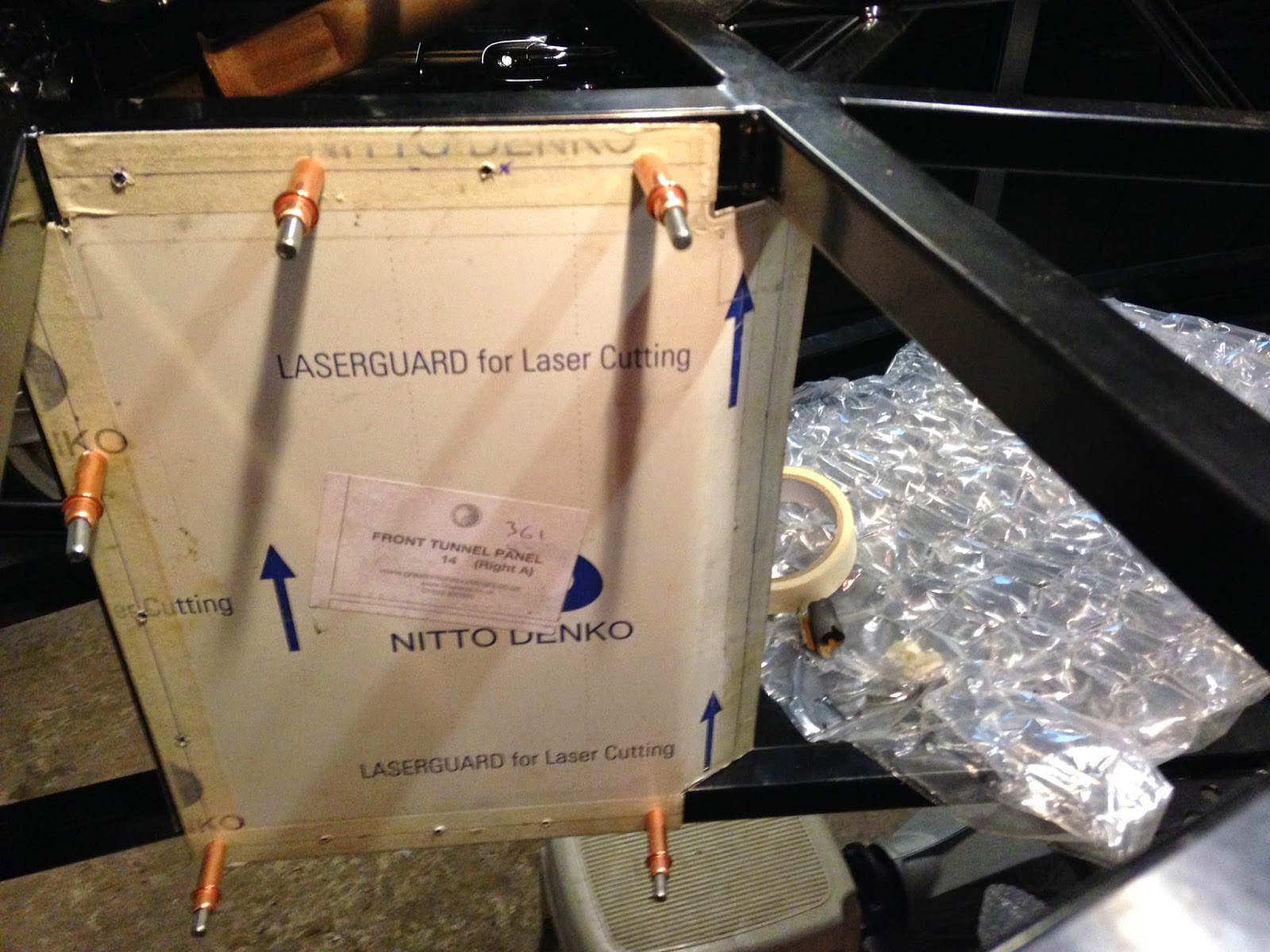
  • locate the hole in the last under section tab, and make sure you have an appropriate bolt to fit, the hole is roughly cut at 6mm and will need filing out. Locate the corresponding hole in the outer wings, (the bits that will come around to form the sides, and do the same as above).
  • now, without trying to roll anything, bring the two holes together on each side and nut and bolt.
  • The rough rear panel shape is now formed.
  • keeping the the under section straight, a straight edge and marker line is a good idea, starting with the tab you have just bolted, push the sides and tab together drill and rivet. This is quite challenging if you are on your own so a spare pair of hands is useful!
  • continue down the under panel both sides until all BUT the last tab are secured, do not drill this it will be visible - its not covered by the wing.
  • the rear panel should now sit on the under section
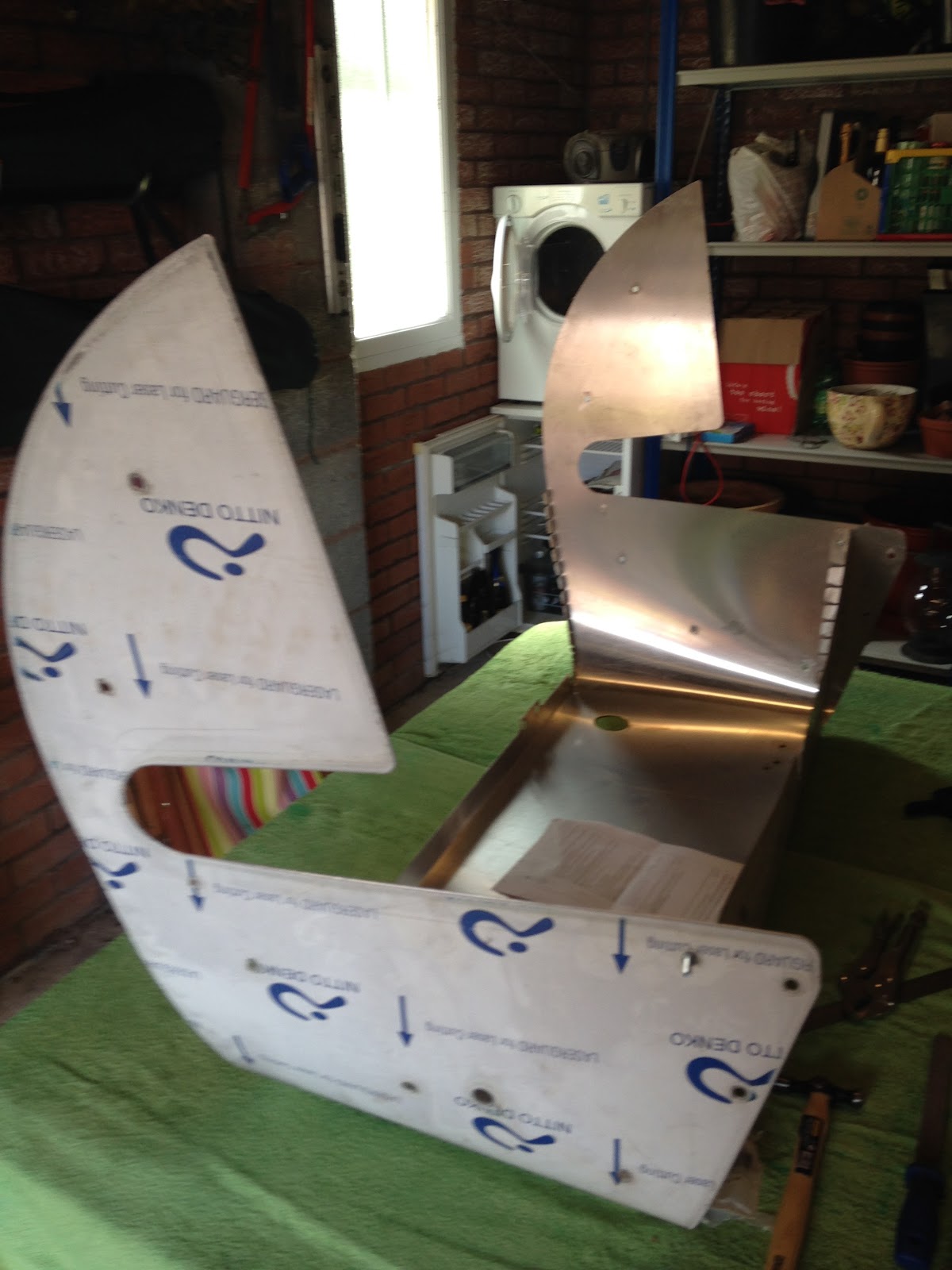
  • now the top panel hoop, which is even more flimsy than the rear panel - be careful with this piece it is visible so any kinks/damage will be seen
  • find the centre of the rear panel and the hoop, position rear and hoop together with bolts.
  • align the hoop to rear panel matching the center marks so that rear panel is slightly proud of the hoop
  • clamp the parts together at each point you drill and and secure with Cleco's, continue across the rear.
  • manipulate the sides so that the side radius matches the hoop radius, again the sides should be slightly proud of the hoop. Again a spare pair of hands is useful otherwise use some quick clamps to hold in position whilst you drill and Cleco

Doing the above will form the panel - as the pictures below I hope prove..
The whole process should not be rushed and I spent a good part of the day doing this task - overall pleased with the result and compared to the scuttle on reflection, I think the rear panel is easier to do - the instructions from GBS were spot on and I would recommend this method over other methods which fellow builders have adopted - each to their own, they have all achieved an end result.


Friday, 13 November 2015

Side Panels

Well, I took the plunge of getting the side panels fitted to the vehicle.

These along with the scuttle and rear panel are what I would class as landmark fitments in the build process, it starts to evolve into looking like a car, becomes more substantial less skeletal even.

Again I spent alot of deliberation as to when these were to be fitted - the factory fit them early in the build so it seemed sensible to take guidance from them, they do after all build these cars to a very high standard and in theory have fined tuned the build sequence over the years.

but you weigh that up with the fact that fitting the panels reduces access around the vehicle and installing items such as the engine / gearbox that bit more tricky. 

Consensus from other builders is firmly down the middle, with I would say an even split of those whom fit early to those whom leave until the last possible minute. so no guide to fall back on there! A decision had to be made so I elected to go with an early fitment simply because fitting whilst it is on trestles is easier, storage of the panels was a problem as I did not want them damaged and items such as the front suspension need removing before fitment so doing that later in the build when the vehicle is off trestles would I envisage prove more difficult...we shall see further down the line if this decision is the right one!

fitment of the panels is superb, alot better than I expected, the panels basically fit like a glove round the chassis frame, no trimming needed, a slight bend is needed mid way down the side but that virtually bends itself into position when the whole panel is mated to the chassis.

Out with the polyurethane sealant of which you will need a lot! position the panel and clamp into position.

I elected to do as few rivets as possible (The factory apparently don't even rivet) so I riveted along the front edge near the front suspension, underneath where the panel folds under the chassis and along the rear where the wheel arch will fit.

Leave to cure for a couple of days and hey presto side panels on, no turning back now and I have to say its started to look like a "proper" chassis.


Sunday, 8 February 2015

Front tunnel panel

So, footwell panels in and ready for sealing watertight I moved onto the drivers side front tunnel panel, one of the few panels which actually needs a slight fold inwards.

Clearly the builder has the discretion to fit this panel either on the inside of the footwell or on the outside transmission tunnel side to provide some more space for feet which considering there is a clutch and brake pedal making it tight for the driver, locating on the outside is a no-brainer which thus creates the need for a fold to be made along the edge.
So same process as for footwell in terms of fitment to the chassis. Once all holes were drilled into the panel and deburred I offered it up to the frame and decided to evolve the chassis drilling part further from the method I adopted with the footwell panels. 

This time I marked up masking tape on the chassis frame, put a pen through the holes in the panel and marked the tape. Centre punched the pen marks, took a pilot drill and drilled through the pen marks and followed up with the 3.2mm drill bit. verdict...An improvement on the footwell drilling process but still not 100% happy however I feel this technique is better.

Next I looked at putting the fold into the edge of this panel to turn it in towards the inside of drivers cockpit. Relatively easy bit this, find some long wood, fix into vice along with the panel and ease the panel over the wood. A few test fits and further bends and the fold is in and the panel is ready for final fit once all the laser protective film is removed.


Footwell Panels final fix

The continuing cold weather makes evening opportunities to work on the car limited, so time and progress has been slightly hampered this past week, that aside I managed to get in to the garage and make further progress with the footwell panels.

One thing I have discovered in the fitment of the panels is you need a ready supply of 3.2mm drill bits! clearly I am still learning the knack for drilling the chassis but what I have established is:

  • You need a good centre punch to give the drill bit a chance to bite into the steel otherwise it will wander across the powdercoat, plus,
  • You need low revs on the drill, high revs and the drill bit will blunt making the job hard nigh on impossible

So with that thought process in mind, I managed to drill into the chassis frame using the panel initially as a guide to mark the holes in the frame which I then centre punched and followed up with steady low rev drilling. Cleco'd the panel as I progressed to ensure it all remained square and true in the chassis.

Once drilled, everything was cleaned with white spirit, the laser protective film removed and time to crack open the black polyurethane sealant


The sealant.... you need disposable gloves without question, get it on your hands and if not removed immediately with white spirit it will stain your skin and however much scrubbing you do after it will remain ingrained for days after. The sealant is also extremely sticky, it grabs the steel virtually immediately but you do have some time to maneuvere into final position.


I elected to run a thick bead down the middle of each side over the drilled holes in the chassis. Inserted the rivet and gunned the rivet in cleaning excess sealant up with a white spirit soaked cloth.

I need to follow up with sealing the inside of the footwells once it they have fully dried to make it all water tight.


Sunday, 25 January 2015

Footwell panels

One of my early tasks is to get the brake lines, fuel pipes and wiring loom fixed into the chassis before all the panels start to be fitted as once they go in access will begin to reduce. That aside the footwell panels are some which can be fitted early on with little impact on future tasks plus on reflection they need to go in early as front brake lines will be fixed into position on the top edges of these panels.

As a confidence builder they are on the face of it straight forward to fit!

A lot of the panels are already pre-cut to size and shape however the first challenge I found was actually getting the footwell panels into position - a little Chinese puzzle to tease me

for future reference the best way to get these panels into position is through the sides of the chassis frame placing the bottom left corner of each panel into its final position and hinging the whole panel round and into situ (I hope that makes sense and yes it did take me a good ten minutes to realise that was the obvious way to do it!).

You will need to do some filing of edges and corners to get a better fit since being laser cut they don't take account of weld lines on the chassis which protrude - however there should not be too much filing to worry about and overall they fitted well.


Basic process I adopted:
  1. file panel and dry fit into position 
  2. using masking tape mark out around the edges of the panel the chassis frame
  3. find the middle of the tape and equally space holes for drilling
  4. drill through with 3.2mm titanium drill
  5. Debur the reverse side with a countersunk drill bit
  6. Offer panel up and clamp ready for Cleco pins, further drilling, final glue and rivet


So Polyurethane Sealant and Cleco kit on order, the final fixing into position beckons...