Showing posts with label panel. Show all posts

Saturday, 15 June 2019

Speedo Sensor

 This is fiddly! Fat fingers are not helpful for this.

Its also helpful the handbrake cable is moved out of the way whilst you do this.

the speedo bracket was fitted relatively early doors in the build. If you avid readers will recollect the hole the sensor goes through was elongated to provide for movement up and down relative to where the driveshaft bolt passes the sensor head.

The distance between the driveshaft bolt and the sensor is between 1 and 2mm above the bolt heads so make a trust template to that depth and place it on top of the bolt. Pass the sensor through the bracket and here is the fiddly bit. It is held in place with a nut top and bottom between the bracket... the bottom nut is extremely faffy to get in place without losing it down the drive-train tunnel.

Once the bottom nut is on you can adjust accordingly with the template to guise the sensor to the right depth by turn the top nut accordingly.


Exhaust

Been waiting on a stock of exhausts to come into Kitspares so it was good to receive this new exhaust through the post earlier in the week, together with the exhaust mounting bracket.

Apart from some exhaust paste (thanks Halfords!) before you can fit the exhaust to the manifold you will have to saw two slits into the manifold pipes approx 4cm long. This will enable the manifold to contract when you slide the exhaust onto the end of it.

Once you have the exhaust in position you can mark where the exhaust bracket fits relative to the exhaust outlet, take it all apart and then.... realise you will have to also take out the passenger seat to drill the holes!

Initial pilot holes from underneath then opened out from above. The bracket fits into place with Nyloc nut and bolts. remember to apply the nut from underneath in the unlikely event it comes off the bolt will still remain in holding the bracket on!

Put the passenger seat back in, re-fix the seat belt - what a faff, something else to add to the growing list of "Don't get too far ahead without seeing whats coming down the line to fit" list.

Apply the exhaust paste, push the exhaust onto the manifold and clamp in with the exhaust clamp wiping away any excess paste. Apply the exhaust spring to the bracket, exhaust outlet and hey presto one exhaust fitted.

Looking more like a car now!


Sunday, 10 March 2019

Wiper motor

 Although I'm not fitting a windscreen until after the car has been IVA'd I need to understand where the wiper mechanism fits relative to the space needed for the ECU. In all likelihood this will come out again before it gets IVA'd but at least it will be a straight forward refit when I come to do the windscreen.

All the bits are courtesy of GBS via their kitspares dept, first thing you will need to do is reverse the mechanism where the wipers park. GBS do a very helpful fact sheet to do this which I wont go into huge detail here suffice to say its a straight forward enough task once you've managed to remove the c-clips.

Back to the installation and another bit you will have to trim down to size is the threaded shaft which extends from the mechanism and the metal sheath which goes over it.

What I did not realise when I did this initially cut down of the sheath and threaded shaft is the sheath has to be cut into several bits to accommodate the wiper boss which goes through the bulkhead and onto which the wipers fit. Reflecting back this was obvious as clearly the boss would not work if it is fitted over the sheath! 

So shaft and sheath trim to size its simply a case of bolting the mechanism to the bulkhead and securing the wiper bosses to the threaded shaft. The Clamp which holds the mechanism in place on the bulkhead is a tight fit and whilst it learns to take the shape of the mechanism it will take some coercing with the nut bolt to stay in place. It gets there eventually but I discovered some new dexterity I needed to apply to the mechanism, Clamp and nut/bolt!


Saturday, 19 January 2019

Exhaust exit from bonnet

Still focused around the bonnet area of the build, attention turned to the aperture which needs cutting in the bonnet for the exhaust manifold to come through.

First thing was to fit the manifold into position using the stock ford gasket and bolts sourced from GBS (Note the stock OEM bolts are too long for the GBS manifold). Simple job end result thus:


now that was in position I could start taking some measurements and datums for where the exhaust exits the bonnet relative to the chassis. I used a piece of paper to mark and make a template which in turn I transposed that onto the side of the bonnet. 

Clearly marked it was a case of taking a drill bit and drilling alot of holes around the perimeter of the the cutting and then using a junior hacksaw blade sawing through each hole to cut out the unwanted piece of metal.

Once removed it was a case of taking a metal file and cleaning up the outline and making a nice smooth finish. Apply some edging strip and one aperture cut int he bonnet to provide an exit for the exhaust manifold.


NB - the eagle eyed readers among you will note the bonnet has suddenly been wrapped in this sequence of photos! I adopted the carbon fibre look for the bonnet and when doing it forgot to take the photos, so only the finished article to note in the pictures. 


Sunday, 29 July 2018

Bonnet - Initial Fit

Its getting to the point where I need to see how the bonnet fits in relation to the scuttle and nosecone. 

Before fitting I attached the bonnet edging trim to both ends which simply knocks in with a rubber mallet (there is a thin bead of glue inside the trim to adhere to the bonnet edge).

I then offered the bonnet up to the scuttle and nosecone (this is temporarily fitted into position) and ratchet strapped front and aft to enable it to form to the shape. Initial indications seem ok - it is slightly proud along the front edges on both sides where the curve is not fully following the curvature of the nosecone . Fit to the scuttle seems good with no obvious area where it is sitting proud.

Clearly some fine tuning to be done and hopefully the gaping referred to above will resolve with the fitment of the bonnet catches and bonnet locating pins...


Saturday, 9 June 2018

Auxiliary Control Panel

Simple job for a Saturday morning, took the opportunity to drill the holes and position the auxiliary switches into the lower instrument panel.

The beauty of the kitcar is each one is individual. I elected to fit the 12v socket, fog lamp and horn switches tot he panel but have for now left room for a starter button which i also fancy fitting (probably when Iva'd and on the road)


so with the switches selected and layout marked out on the panel, time to get to work with the stepped drill bit and carefully drill the holes not getting too carried away with drilling too much!! - little steps and keep checking until each switch fitted nicely through.

Clean up the swarf, remove the masking tape and hey presto holes drilled ready for the switches


Sunday, 27 November 2016

Access Panel - boot floor

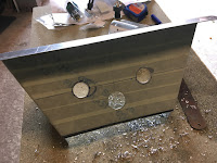
I have noted on many builds the need for an access panel in the boot area to get to the differential, fuel pump etc. I cant seem to track down a part at GBS - they supply the boot panels (see earlier post) but the floor panel is solid and needs cutting out.

So, no option but to get the jigsaw out and cut out a hole in the panel and fit a new piece over it secured with x4 rivnuts and bolts.

a nice little fabricating job - sourced some metal sheet off ebay which will provide the new floor, cut that to size, filed and trimmed. 

Added some window insulating tape round the edges to provide a seal and secured into position with the freshly drilled rivnuts/bolts.

looks good (although not the best photos, poor light!)


Sunday, 21 August 2016

Rear Boot / storage area

Focus is on moving back to front with the build, rear panel has been successfully vinyl wrapped and permanently fixed into position (no going back on that decision now!)

I have a nice bare area aka "the boot" which needs completing and there is nothing of significance left to do on the rear end which is preventing me from focusing on getting the boot to a finished position.

GBS do the rear boot panel kit (luggage infill panel kit) which comprises:


Differential inspection panel (needs a hole cutting out)
x2 inner closing panels 
x2 rear closing panels

Looking at the panels it is relatively self evident where they fit, the main area of work is in cutting an access hole through the differential inspection panel to create access to the rear diff, brake lines etc (this is required for IVA in the UK as the testers will want to look in this area)

Simple jigsaw job of cutting through the panel, drilling four holes and inserting rivnuts through the holes. You will need a further piece of metal to cover over the hole you have just cut ( I need to get this still!)

Another piece of work which needs doing is to drill a hole in the rear closing panels near the top, to provide access to the retaining nut/bolt for the rear shock absorber. I appreciate it is unlikely there will be a need to remove the shock however I want to build some "future proofing" into the build on the off chance access is required. Again a simple process of using a step drill to drill through the panel to give a big enough hole to accept a socket.

Once all the above is done its a case of put with the polyurethane sealant and fix the panels into position, start with the differential access panel first, followed by the rear closing panels. 

With the rear closing panel remember to route the fuel sender cable through otherwise the sender will not work!

the inner closing panels looking at the GBS instruction suggests the top section of the panel goes under the steel chassis section - this in my opinion is not possible due to the powder coating changing the profile of the gap the panel goes under. Speaking to GBS about this they confirmed the panels can be just glued access the top of the steel and not to worry to much about the top going under the steel chassis, So over the top the went!

Panel in - ready for carpet laying


Saturday, 9 April 2016

Rear Panel - Part 1

Well, the time has come... I have to bite the bullet and give consideration to fitting what most builders consider the hardest piece of the zero build - forming and fitting the rear panel.

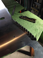
It looks daunting when you see the single largest piece of steel flat on the floor and I profess to have spent alot of time reading fellow build blogs, studying photos and basically building up the courage to jump in and get the panel formed.

After reading the various blogs and techniques I also asked the factory how they did it more to confirm some understanding but I guess to see if they had any secret alchemy they used to create this major panel.

Truth be told.. the GBS way of of construction was what I ultimately followed and I will share with you below the technique they used.

So one Saturday set aside with no distractions, plenty of space time to build a rear panel:
  • I covered the patio table with some old carpet/towels and sat the rear panel onto the table top - back down. the panel is quite weak so make sure it is evenly supported.
  • First thing, do not try and roll the side at this point, you need to do some prep work before some bends are put into the panel. 
  • The tabs along the top edge and sides of the under section need bending 90deg, the top edge toward the front of the car, the under section upward. Precision doing this will help later. bend from the bottom of the slots.
  • locate the hole in the last under section tab, and make sure you have an appropriate bolt to fit, the hole is roughly cut at 6mm and will need filing out. Locate the corresponding hole in the outer wings, (the bits that will come around to form the sides, and do the same as above).
  • now, without trying to roll anything, bring the two holes together on each side and nut and bolt.
  • The rough rear panel shape is now formed.
  • keeping the the under section straight, a straight edge and marker line is a good idea, starting with the tab you have just bolted, push the sides and tab together drill and rivet. This is quite challenging if you are on your own so a spare pair of hands is useful!
  • continue down the under panel both sides until all BUT the last tab are secured, do not drill this it will be visible - its not covered by the wing.
  • the rear panel should now sit on the under section
  • now the top panel hoop, which is even more flimsy than the rear panel - be careful with this piece it is visible so any kinks/damage will be seen
  • find the centre of the rear panel and the hoop, position rear and hoop together with bolts.
  • align the hoop to rear panel matching the center marks so that rear panel is slightly proud of the hoop
  • clamp the parts together at each point you drill and and secure with Cleco's, continue across the rear.
  • manipulate the sides so that the side radius matches the hoop radius, again the sides should be slightly proud of the hoop. Again a spare pair of hands is useful otherwise use some quick clamps to hold in position whilst you drill and Cleco

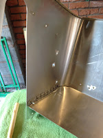
Doing the above will form the panel - as the pictures below I hope prove..
The whole process should not be rushed and I spent a good part of the day doing this task - overall pleased with the result and compared to the scuttle on reflection, I think the rear panel is easier to do - the instructions from GBS were spot on and I would recommend this method over other methods which fellow builders have adopted - each to their own, they have all achieved an end result.


Saturday, 30 January 2016

Pedalbox

Whilst the scuttle is in position I had a look at the pedalbox since fundamentally it looks straightforward to fit and with little work required to be done.

To complete it, so to speak, it needs 10 M8 rivnuts fitting, and simply positioning screwing into place on the chassis, firewall.

first challenge and one which I had noted on other builds - the throttle pedal screw on initial fit does not fit straight into the locating hole in chassis - very puzzling.... 


Solution is quite straightforward and a light bulb moment sat in bed drew me to the folds in the pedalbox base where it folds out to lay flat on the chassis. Simply put, the folds need tightening - so taking a toffee hammer to the fold and using a straight edge (steel rule) - tap along each fold line to tighten the fold to a defined right angle. place back in position on the chassis, push the throttle bolt through the pedal box into the chassis frame and bingo it goes in straight - result!


The box will need some selective trimming and bending dependent on respective fit to firewall and chassis but overall as mentioned earlier this is a nice quick job to do.

M8 rivnuts applied to the top edge of the box where the lid fixes in position and also along the bottom edge into the chassis frame (be careful, these holes are quite close to the edge of the chassis frame). Finally a couple of further holes to secure into the firewall and job done its fitted.


Monday, 18 January 2016

Scuttle Part 2

So initial form and fit of the scuttle has been done, attention now turns to fitting the flimsy dashboard rail. At this point it struck me that in hindsight it was perhaps best to fit this piece before fitting to the firewall - It provides the best template for forming the shape of the scuttle and fitting it after the firewall in my opinion is harder. Live and learn, not a showstopper by any means but just a more awkward fit in my opinion.

Off with the scuttle and firewall which, having been sat screwed into the chassis for a few days had now assumed a nice curved shape and did not spring out as soon as I released it from the chassis. I laid the pre-formed scuttle onto a workmate and positioned the dashboard rail ensuring the centre tab of the rail matched with a mark on the centre of the scuttle top.

The rail is ultimately riveted into position. This is where you need to be very careful drilling as the rivets will be covered by "tadpole" trim in due course so they need to be very close to the edge of the scuttle. Wandering drill bit is not what is wanted at this stage.

I worked from the underneath, drilling outwards and cleco'ing in position, moving outwards from the centre, left, right, left right each time. The sides were more of a challenge to form round the rail but mission accomplished with some elbow grease and mole grips as an additional hand to help hold things in position.

Overall approx 1 hours work, worth going nice and steady with this task as its flimsy and bends very easy. Drilling needs to be quite precise and you need to be ambidextrous at times bending and pulling together the scuttle sides / dashboard rail.

Putting the dash rail in makes the structure alot more sturdy - relocating back to the chassis was alot easier this time as the shape was already preformed but more importantly robust - I left it in position a few nights before applying the polyurethane sealant to the rear of the firewall, ratchet strapping the scuttle maintains shape and form.

I made reference in the first scuttle post about the top corner of the firewall pushing backwards on the driver side - releasing the scuttle to apply the dash rail resolved this problem as when I came to refit it was much better and maintained its shape.

So ratchet strapped up, glued up along the rear of the firewall, leave it all to cure off nice and hard for a few days - scuttle just needs the front tabs trimming off and the clecos replaced with rivets along the dashrail - job done.

Overall pleased with how this has turned out - certainly looks more like a car now the scuttle is in position - need to look at the pedal box now and get that dry fitted.