Tuesday, 26 May 2015

rear upper wishbones

As a change I decided to look at the rear suspension and start tackling the mountain of plastic bushes which need inserting into the suspension arms.

Process is extremely similar to what I explained in my earlier blog post on the pedals however to recap:

  • Using a sanding drill bit clean out the powdercoat from the inside of the suspension 
  • File any weld protrusions evident inside the suspension arms where the bushes will be inserted
  • Chamfer the plastic bush to assist inserting into the suspension arm
  • Apply copper grease on the inside the suspension arm and the outside of the plastic bush
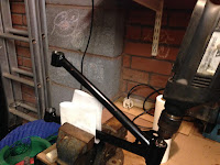
  • using a vice squeeze the bush into the suspension arm being conscious not to damage the face of the plastic bush with the vice teeth.

6 down, 22 to go on the rear...a repetitive task!


Once these are done, the steel inserts can be put into the bushes again using some copper grease to ease it in with the help of the vice. You may need to clean out the insides of the plastic bushes before you insert the steel collar.

You also need to ensure the collar sits flush with the plastic bush face, if they protrude file or grind down to achieve the desired fit.

Not quite as repetitive... thankfully only 6 to do

There are obvious left and right wishbones, standing at the rear of the chassis, the wishbones with a notch fix to the right hand side. You will also need to remove the flexible brake hose if already fitted to allow access for the bolts through the chassis and wishbones.

Penny washers need inserting between the plastic bushes and the chassis lugs through which the bolts pass through, smaller washers on the outside of the lug between bolt head and nyloc nut. All loosely fitted for now, however they will need torquing to 90nm before slackening off and tightening 15nm followed by a further quarter turn.


Friday, 22 May 2015

Fuel lines Part 2

Now the fuel lines are in situ I can my attention to connecting the front of the lines onto the swirl pot.

This is achieved via rubber fuel hose which is jubilee clipped between the plastic fuel lines and the swirl pot.

Cut the fuel line to your desired length, insert some brass collars to re-enforce the end of the fuel line where the rubber hose will insert onto and apply a jubilee clip to the rubber hose/plastic fuel line as well as one at the end where it connects to the swirl pot (remember to orientate the jubilee clip so it is accessible from above)

At the moment, I have kept the rubber fuel hose probably longer than needed, subject to space I may revisit this later in the build and adjust accordingly, being a fully paid up member of the school of measure twice cut once - we generally learn the hard way with these details!

I also want to get a plastic cradle / cable tie riveted to the driver side transmission tunnel to provide a further anchor point for the fuel line as it drops down from the brake line.


**update

As alluded to earlier, a change of plan with the hose routing and as usual the answer is obvious! - I have re-routed the top pipe to nearer the brake line thus splitting the red/black fuel lines higher up. A fixing is still needed for the red fuel line but overall more happy with this arrangement (probably still need to shorten the other fuel hose at some point..)


Fuel lines part 1

Including under what I generically call "plumbing", now brake lines have been fixed into position next part of the plumbing is to run the fuel line down the transmission tunnel front to rear and connect to the Swirl Pot.

The fuel lines are simple enough to install and basically run alongside the brake lines fixed into position with cable ties. There is plenty of fuel line provided so balance out front to rear and fix into position either side of the P-clips holding the brake line to the chassis frame.

Where it does get tight is around the rear seat panel / differential / handbrake cable area where plastic protective conduit is needed to shield the pipes from the obvious movement of parts. 

When the drivers side transmission tunnel is fixed into position the conduit will be fixed to the panel via plastic saddle, cable tie riveted to the panel.

The front lines connect to the Swirl Pot whilst the rear plumbs into the fuel pump and fuel tank.


Sunday, 10 May 2015

High pressure fuel pump

Now the low pump arrangement is in place, attention turns to the front and a nice quick job of installing the high pressure fuel pump which feeds fuel from the swirl pot.

Looking at the fixings and how substantial the pump is I am skeptical of the fixings being strong enough for the fuel pump, this has been installed as per the factory suggestion so who am I to critique however I cannot help but think a more robust solution maybe needed...time will tell on that one i guess!

back to the installation, its held in place by cable ties and plastic cradle riveted to the drivers footwell panel. Simple installation, 3.2mm drill bit, two rivets, x2 plastic cradles with the cable ties threaded through the cradles, fixed in position ready for the pump;

The pump is tightly cable tied into position but be aware to ensure the top cable tie is below the lip of the outer casing of the pump as when you come to fix the rubber fuel pipe into the base of the pump the whole pump wants to push up and pop out of the cable ties! - again this feeds more skepticism that this is the best fixing solution....


Once this is in position you can now fix the rubber fuel hose from the base of the fuel pump to the swirl pot, quite straight forward only need to be aware of ensuring there is no kink in the curve of the hose between the pump / swirl pot and also to ensure when tightening the jubilee clips holding the hose in place to make sure the screw is accessible from above!